Introduction
Oftentimes, it is desirable for a system to be able to dynamically control the FPGA logic resets in software. There are a number of reasons for this, but throughout my career, I have found that when developing and testing the software for an FPGA, you often may run into situations where due to mistakes in your software, the PL logic locks up and you need to issue a reset. Sure, you can simply power cycle the board, correct the issue and try again – but this takes away precious time from your software development iterations. There also might be requirements in your system that at runtime, the software application must dynamically issue a reset.
AMD’s ZynqUltrascale+ SoC has x4 dedicated reset signals intended for use to reset custom PL logic in the device. In this article, we will be exploring how these normally function, and how the software developer can manually control the signals to issue a reset to any connected PL logic. We will be showing demonstrable examples on the Avnet ZUBoard-1CG as well.
Prerequisites
This article will not go through all steps needed to create the Vivado and PetaLinux projects. It also assumes you have some basic knowledge of working with the ZynqUltrascale+. Some very helpful articles on these basic concepts can be found here:
https://www.hackster.io/adam-taylor/getting-started-with-the-zuboard-vivado-and-vitis-13483e
https://www.hackster.io/whitney-knitter/getting-started-with-avnet-s-zuboard-1cg-f1d793
PL Reset Signals
If we start by digging into UG1085 (Zynq Ultrascale+ Device Technical Reference Manual), we will find that these reset signals are mapped to specific GPIOs in the PS GPIO controller.
“The AMD software and hardware design tools assign functionality to GPIO channels. For example, the tools define four GPIO [92:95] channels routed to the EMIO for resets to user-defined logic in the PL.”
https://docs.amd.com/r/en-US/ug1085-zynq-ultrascale-trm/SDK-and-Hardware-Design
The manual further goes on to explain how these signals are mapped from the GPIO numbers to the reset numbers:
“Up to four outputs for GPIO[92:95] can act as reset signals to user-defined logic in the PL. The number of GPIO EMIO signals depends on the number of PL fabric resets selected in the Vivado PS configuration wizard (PCW). For example, if one reset is selected, GPIO[95] is assigned as a reset signal. If two are selected, then GPIO[95:94] are assigned.”
From UG1137, we can also see the normal low level AMD software behavior of these reset lines:
“The pl_resetn signals are implemented with PS GPIOs. Pl_resetn pins are released after bitstream configuration in software using the psu_ps_pl_reset_config_data function.”
https://docs.amd.com/r/en-US/ug1137-zynq-ultrascale-mpsoc-swdev/GPIO-Reset-to-PL
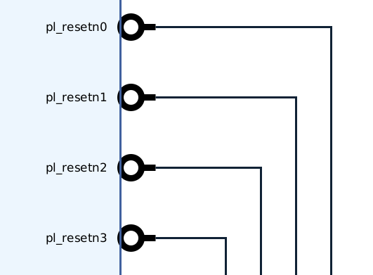
We can thus infer that the mapping for all resets is as follows:
| EMIO GPIO Number | Reset Signal |
| 95 | pl_resetn0 |
| 94 | pl_resetn1 |
| 93 | pl_resetn2 |
| 92 | pl_resetn3 |
Armed with this knowledge, we can begin the steps of issuing a reset to the PL logic by controlling the IO(s). Note that in order to do this, you must have a design where 1 or more reset signals is hooked up from the pl_resetnX output to your PL logic and doing so would not lock up your system because of some other dependency of your processor or software on any PL resources.
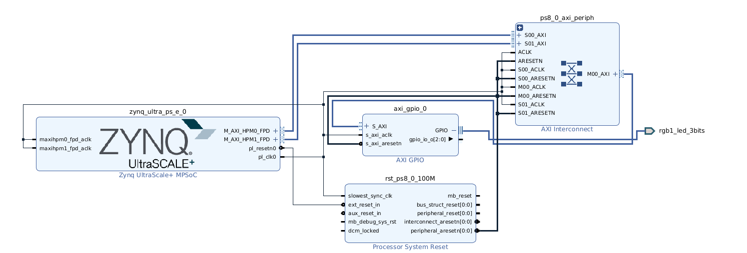
To demonstrate this, I have created a very simple project with an AXI GPIO mapped to the lines of the RGB LED on the Avnet ZUBoard-1CG board. pl_resetn0 is connected such that driving it will reset the AXI GPIO IP instance. Using this design, we will configure the GPIO to output to the LED, and then issue a reset and demonstrate how the IP is restored to its default state.
We will demonstrate this example in Linux as this is a common use case on the ZU+. In addition, Linux makes it very easy for the user to try this given the large sets of utilities such as libgpiod-tools. These examples can however also be easily extended to Vitis, and I will add some helpful hints for this at the end.
As alluded to above, we will be using the libgpiod interface in Linux with the libgpiod-tools utilities (gpioset, gpioget, etc.). If you are not yet familiar with this interface as compared to the kernel legacy GPIO interface, please take a short read at the following README from the library itself:
https://github.com/brgl/libgpiod/blob/master/README
Here are the controller line to interface line mappings:
| Linux “Chip” GPIO Line Numbers | GPIO Interfaces |
| [0:77] | MIO GPIOs [0:77] |
| [78:173] | PL EMIO GPIOs [0:95] |
Given the previous explanation about the reset IO mapping within the PL EMIO GPIOs, we can then determine that the Linux GPIO line numbers for are chip are mapped to the resets as follows:
| Linux “Chip” GPIO Line Numbers | Reset Signal |
| 173 | pl_resetn0 |
| 172 | pl_resetn1 |
| 171 | pl_resetn2 |
| 170 | pl_resetn3 |
Thus in our example design, we can drive line 173 low and high again to issue a reset.
To give this a try, let us start by setting one of the outputs on our AXI GPIO to light the green LED on the board. This way, when we issue the reset, we should see the LED turn off since the IP will be restored to its HW configured default state of outputs low.
We begin by using gpiodetect to determine which GPIO chip matches which controller:
root@petalinux-emio-reset:~# gpiodetect
gpiochip0 [firmware:zynqmp-firmware:gpio] (4 lines)
gpiochip1 [a0000000.gpio] (3 lines)
gpiochip2 [zynqmp_gpio] (174 lines)
As the output shows, gpiochip1 is our AXI GPIO and gpiochip2 the regular zynqmp_gpio controller mapped to both the MIO and EMIO GPIOs as explained previously.
Thus to light the green LED, we can do the following:
root@petalinux-emio-reset:~# gpioset 1 1=1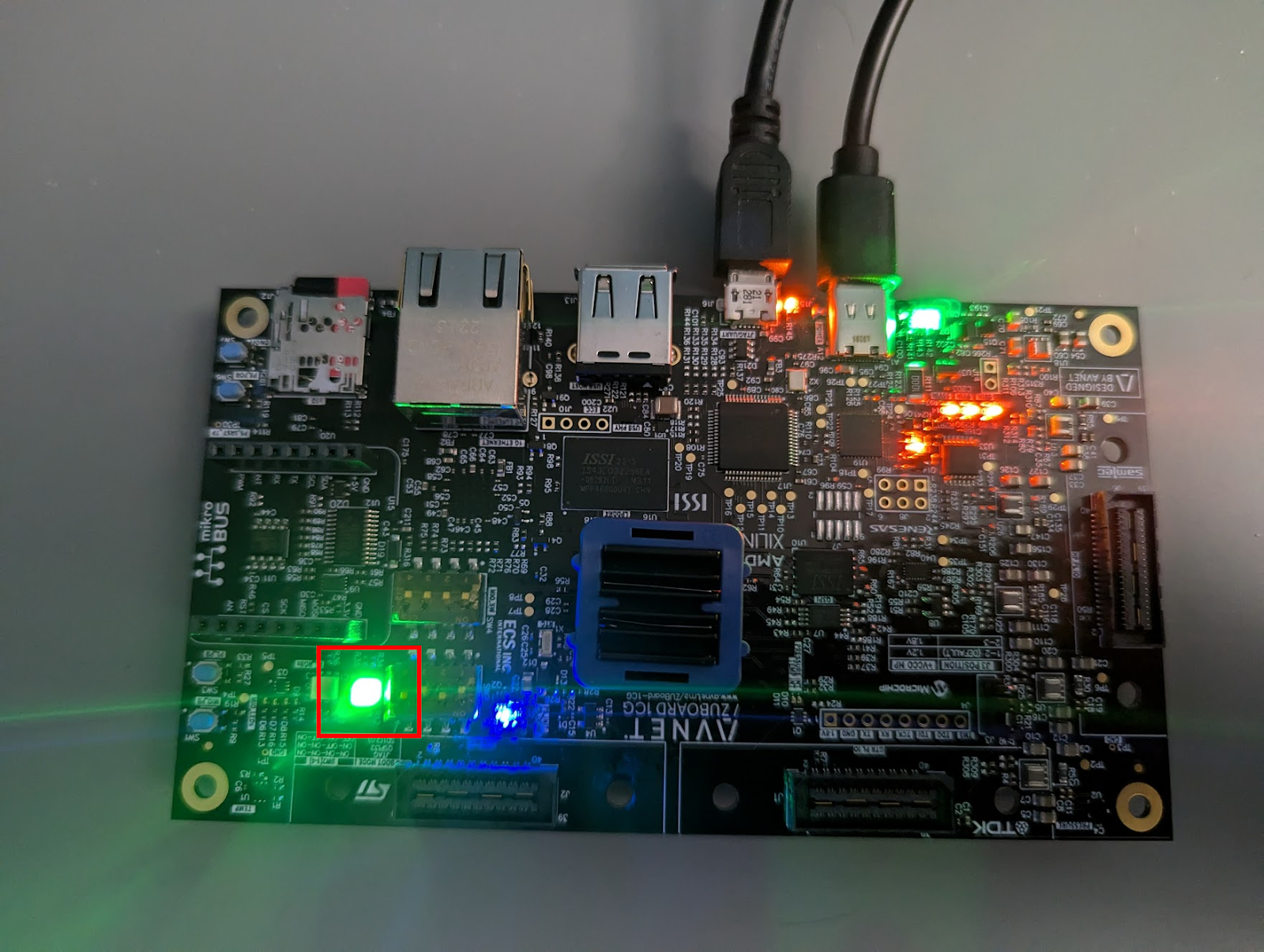
And voila! The LED comes on. Now to issue the reset to the controller. As explained previously, we need to use gpiochip2 to access the appropriate EMIO GPIO – line number 173 in this case. Let us issue the reset:
root@petalinux-emio-reset:~# gpioset 2 173=0
root@petalinux-emio-reset:~# gpioset 2 173=1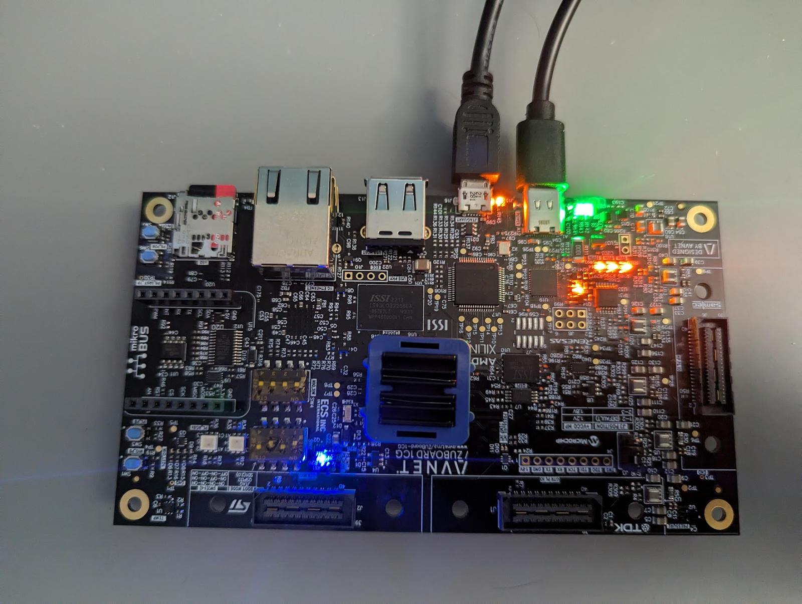
As soon as we drop 173 to 0, the LED turns off! Amazing right? I know, not really that amazing, but we have just demonstrated how to control the PL reset lines.
Note: In the current example using the Linux GPIO interface, this method is a little brute force, as the driver is unaware the controller has been reset. However, it’s a very simple demonstration of the PL reset capability.
Hint: While the example in this post covered controlling these resets in Linux, the same concepts apply in Vitis in bare metal / FreeRTOS. Utilizing the AMD GPIO driver functions, we can use the same GPIO line numbers (i.e. 173) in order to set the value of the reset pins.
I hope that you find this article useful. Please feel free to leave any comments or questions below and I look forward to seeing you in the next technical blog post!